Road building
Mohács Danube Bridge: plans ready for implementation

The construction of a bridge over the Danube near the town of Mohács is a long-standing dream: to replace the current ferry and the Baja bridge, which is 28 kilometres away as the crow flies and therefore represents a significant detour, the construction of a new bridge has been a long-standing desire of the local population, which of course also means the expansion of the national road network.
The permitting and construction designs for the Danube embankment bridge were prepared by FŐMTERV Zrt. (as a subcontractor of Speciálterv Kft., the design for the breakwater bridge was prepared by RING Mérnöki Iroda Kft.).
The publication "The Future of the South-Hungarian Region", published in 1995 by the Mohács Danube Bridge Foundation, dealt in detail with the construction of the bridge on the northern side of the town, indicating the approximate location of the crossing.
The EuroVelo cycle path will also cross the bridge
The feasibility study carried out in 2014, followed by the study carried out between 2019 and 2022, the permit and the design plans identified the location of the intersection on the north side of Mohács. The final design includes three consecutive cable-stayed "network" arch bridges with 270+250+230 m spans, 2×2 road lanes and a 3.30 m wide EuroVelo cycle track over the Danube.
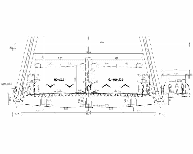
Source of images, graphics: FŐMTERV
The embankment pillar is located close to the left bank of the Danube, while the breakwater pillar is located on the left bank of the dirt road dividing the nature reserve.

The mesh cable pattern allows the structures to have extremely slender cross-sectional dimensions, with an arch cross-section of 1.60×1.60 metres at the centre of the opening (increasing to 3.00 metres towards the ends of the bridge). By optimising the cable pattern, the moments in the arches were significantly reduced and the cable spans were more evenly distributed.

The cross-ties, designed to prevent the arches from bending perpendicular to the plane, were also intended to be a unique visual feature. The dense latticework and lattice bars connected to the arches at a flat angle are, they say, unfortunate from a strength point of view: the cross-connection bars lock at a very flat angle with the required support force and also receive significant forces from the main support effect. This effect has made it most difficult to tie the truss rods into the internal spine plates of the arches. In the end, the forces could be transferred to the bars of a cross-connection with sufficient strength to prevent buckling, but with the optimum stiffness to absorb as little as possible of the main support, by means of a tie plate welded into the cut bar ends.
Remote monitoring system measures temperature, forces and stresses
Both the struts and the arches are non-passable closed cross-section structures with air-tight seams, so the monitoring of the processes inside them will be done by a remote monitoring system designed by the Department of Bridges and Structures of BME as a sub-designer. The system will measure, among other things, air temperature, structural temperature, internal temperature and humidity of closed cross-sections, wind speed and axle weight of passing vehicles, as well as record hinge reaction forces, structure accelerations and mechanical stresses (strains) in the structure at critical locations.
The below-average section of the pier was designed by FŐMTERV with inboard bark elements forming both the working space boundary and the formwork of the pier, in a similar way to the Pentele Bridge piers. In order to reduce the self-weight of the pier and the pile reactions, as well as the amount of concrete to be used, the central part of the pier is of openwork design. The piers supporting the pile are connected by a steel-framed handrail.

Construction requires special lifting equipment
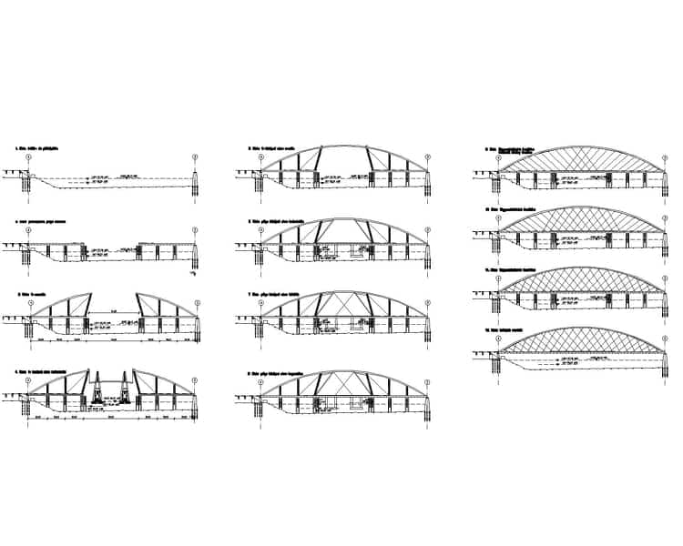
As proposed in the plans, the causeway bridge will be built on temporary supports, leaving an 80-metre-wide shipping lane in the middle of the causeway. To raise the arches, the lifting height of the floating cranes regularly used in Hungary is not sufficient, and therefore requires the use of lifting gear. Temporary inclined outriggers are needed to adjust the shape of the arches.
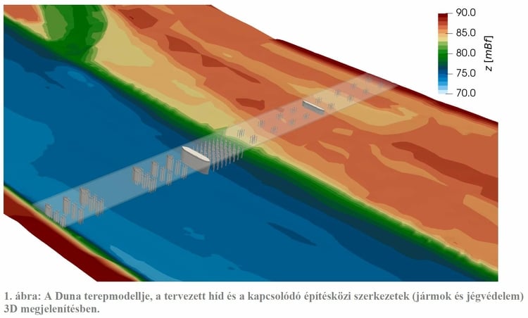
The flow conditions of the Danube are influenced by the riverbed, which was investigated by the Department of Hydraulic Engineering and Water Management of BME in the mid- and high-water conditions, and the measures needed to prevent the riverbed from degenerating were identified.
The Government Decision 1239/2023 (20.VI.) ordered the continuation of the Danube Bridge and the construction of the related road network, lifting the previous suspension, so that the realisation is within reach.
Source : Link








The town centre on the banks of the Tisza is being regenerated

The Market has fulfilled its promise: it has delivered the 10,000 tonnes of natural stone offered for the raising of the bottom sill at Paks

The construction industry is both vast and marvellous – the Duna Group Szabadegyetem has been launched

ESG is now a business issue for suppliers in the construction industry too

Rain gardens are coming to Budafok, with over 3,000 square metres of green space set to be developed

Contemporary art deco in Csopakon

Four new bridges to be built in the heart of the former industrial city

Safer driving on the motorways: new digital signs for the MKIF
-

 Industry news 2026. 08. 18.
Students were introduced to the high-tech construction industry at BME’s field camp in Göd
-
Bound track 2026. 08. 17.
New pedestrian crossings and a junction with traffic lights are being built in Angyalföld
-
What is being built? 2026. 08. 18.
Hungary’s new McDonald’s restaurant has moved into a modernist listed building in the centre of Budapest
-
What is being built? 2026. 08. 18.
New paving, a playground and visitor facilities are being planned for the Várkör area in Pannonhalma