Industry news
Spectacular arches, ingenious solutions – the designers of the FŐMTERV present Venice’s award-winning bridge

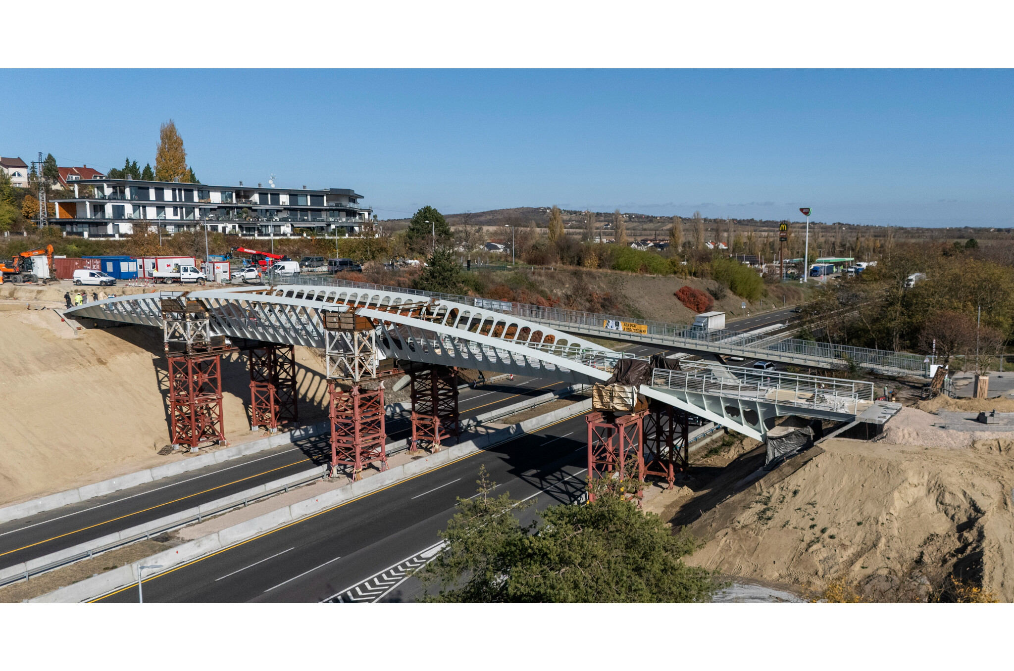
How can a span of nearly eighty metres be bridged in such a way that the construction causes as little disruption as possible to motorway traffic, whilst ensuring the structure is at once slender, aesthetically pleasing, durable and functional? When designing the Venice Bridge, the experts at FŐMTERV had to find answers to these questions. Ádám Balogh, lead designer and project manager, Dr Máté Hazay, chief structural engineer, and Anna Mária Péter, bridge design lead, illustrated the complexity of the design work through the spectacular and hidden details of the award-winning bridge.
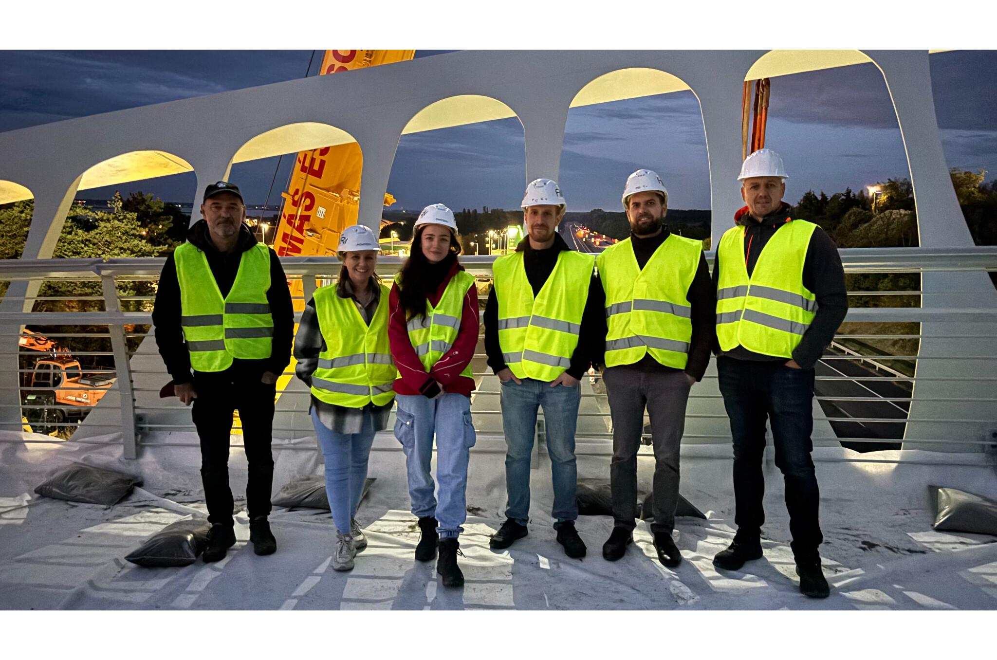
The Magyar Mérnöki Kamara Tartószerkezeti Tagozata award recognised the Venice Bridge in the category of footbridges, whilst the Tomori Pál Bridge was recognised with the Év Tartószerkezete award in the category of road bridges.
Established last year, this award recognises structural engineers who have delivered outstanding engineering achievements. The judging panel highlighted, amongst other things, innovative structural solutions, the economical and sustainable use of materials, and harmonious integration with the architectural concept as key evaluation criteria.
„It was both an honour and a surprise to have won an award in a field that included the biggest names in the Hungarian bridge-building profession, and to have been able to compete against a bridge over the Danube as well”
– Ádám Balogh summarised the reactions of the design team members.
This was not the bridge’s first accolade. Last year, at the Tekla BIM Awards 2025 International Tekla Structures project competition, the bridge – which is currently under construction – took first place in the Infrastructure Project category and also won the public vote.
…he was a real gem to us…
There was very little time available for the design process, and every completed drawing and construction technique had to be perfect, as the manufacture and assembly of the bridge began very soon after the design phase. Anna Mária Péter said:
„The Venice bridge project was a real highlight for us. We gained a great deal, both professionally and personally, and of course we put a great deal of effort into it. You could really sense that it was a shared endeavour for all those involved – and for the entire bridge and structural engineering firm behind us – to create this unique, beautiful bridge to the very highest standard. As design engineers, we rarely have the opportunity to walk across a completed bridge within just a year or two.”
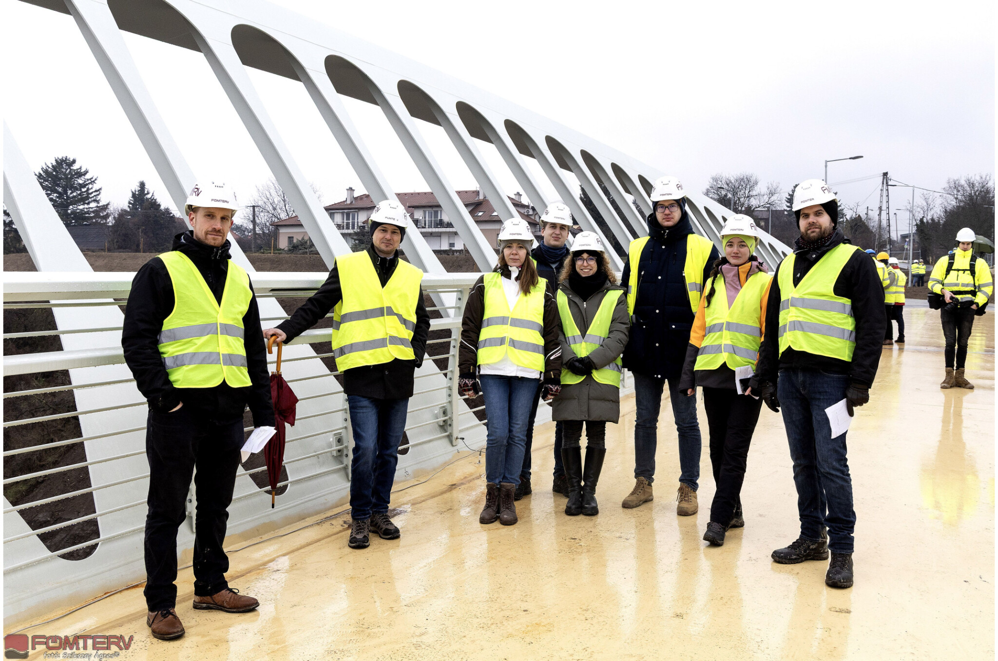
Study plan, design options, modelling and decision-making
Speaking about the design of the bridge’s unique, outward-curving main girder – which has also caught the public’s attention – Ádám Balogh said:
Despite the tight deadline, they endeavoured to draw up a comprehensive design brief. With regard to the bridge structural solutions, the main consideration was to find a solution whose construction would cause the least possible disruption to traffic on the operational motorway.
For this reason, a bridge design involving the construction of an intermediate, deep-foundation pier was rejected from among the structural systems and configurations. The possibility of a three-span solution, with piers positioned alongside the crown edge, was also considered. In this case, the three spans would have been 12, 45 and 23 metres long. The central span would thus have been nearly four times as long as the left-hand end span, which would have resulted in an extremely unfavourable structural ratio.
Of the other variants, the client, in collaboration with MKIF Magyar Koncessziós Infrastruktúra Fejlesztő Zrt., opted for the single-span steel structure. They then examined the design options for the upper and lower deck arch bridges, including their material usage, aesthetics, and static and dynamic behaviour, using parametric models built in Grasshopper.
When designing the bridge, it was necessary to take into account the site conditions, the differing heights of the bridge abutments and other fixed parameters. Of these, Anna Mária Péter highlighted the coordination of the slope design with the requirement for the bridge to have a maximum gradient of 5 per cent as the greatest engineering challenge. The positioning of the supports, the design of the spans, the height of the abutments and the slopes, and the routing of the cycle path onto the bridge are the result of a multifaceted optimisation process.
The final structure is a steel bridge with a curved main girder and a span of nearly 80 metres, the design of which makes the most of the asymmetry dictated by the obstacle it spans.
The load on the foundations was reduced using concealed bracing
The bridge must bear both its own weight and the load of the vehicles travelling across it. As a result of these forces, the arches also exert lateral pressure on their supports. By combining a concealed inclined brace with the bridge’s other structural elements, the designers have ensured that these lateral forces are largely balanced out within the bridge’s structure. The path of these forces is illustrated in the simplified diagram below.
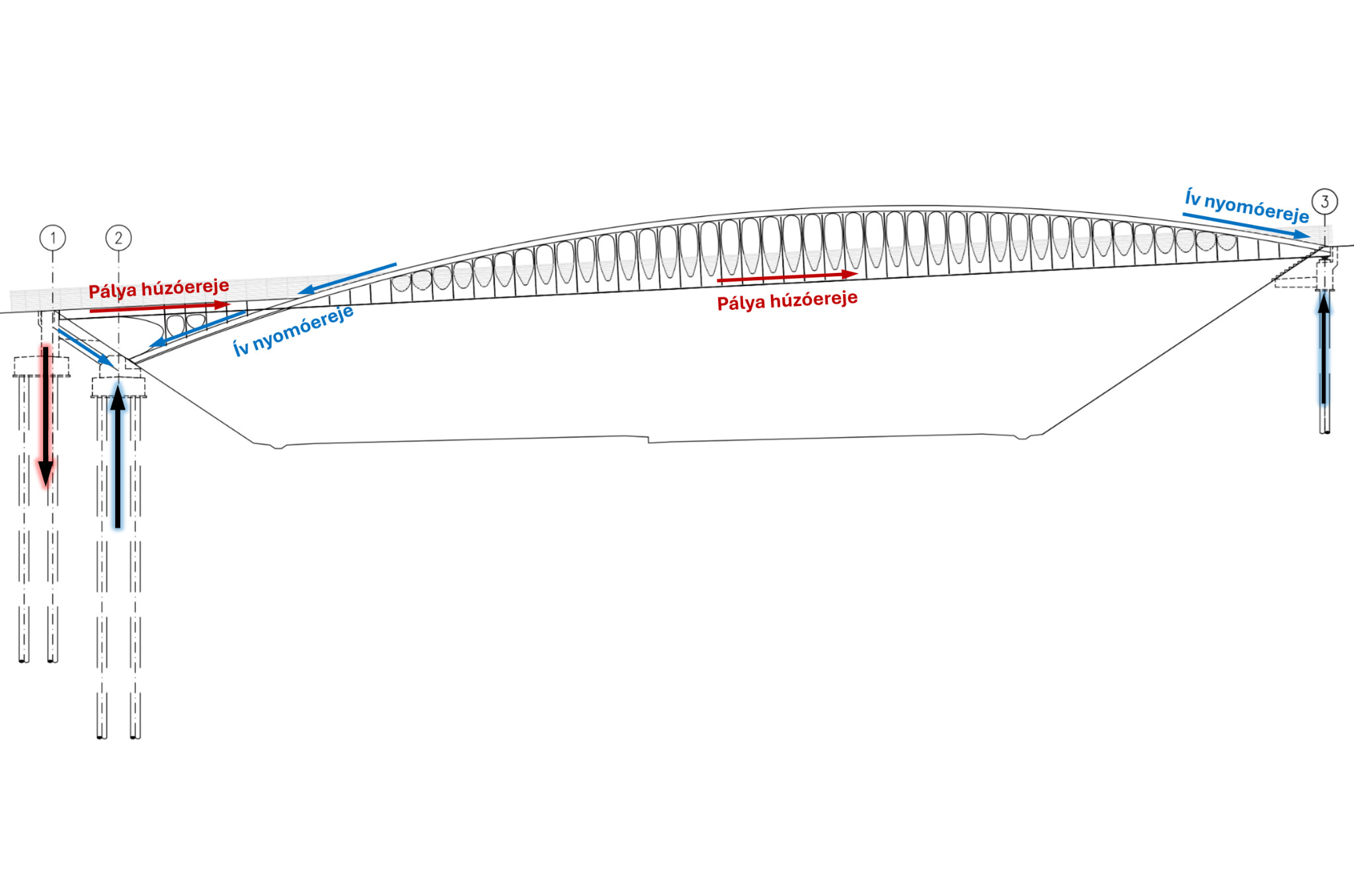
„In the case of a sunken track design adapted to the local terrain, the challenge lies in accommodating the tensile force of approximately 9,000 kN (nearly horizontal) acting on the track structure, which functions as a tie rod for the curves. This could only have been accommodated by a very costly solution given the foundation in the relatively soft embankment. We had to devise a structural system that would eliminate the majority of the horizontal reactions”
– said Máté Hazay.
The chief structural engineer added that what makes their solution unique is that, by means of the prestressed abutment No. 1 and the bracing rod – concealed within the slope – between supports No. 1 and No. 2, they have created a „closed” force system in which the bridge’s foundations are subjected almost exclusively to vertical forces.
Power, impact, bespoke solutions
In addition to the concealed structural solutions, the design of the junctions has also been addressed in a unique way. At the junction between the arched main girders and the stiffening girder, the web of the stiffening girder and the inner web of the arched main girder merge; this connection determined the geometry of both the stiffening girder and the arch.
Máté Hazay highlighted two details of the structural junction design. One task was to transfer the tensile force of the track structure to Abutment 1. The force was transferred via a ribbed end plate to threaded rods passing through the abutment. These were housed in grease-filled sleeves, through which the track’s tensile force was transmitted to the rear of the abutment via a press fit. Subsequently, the upper section of the abutment acts as a short cantilever, transferring this nearly horizontal force to the inclined struts.
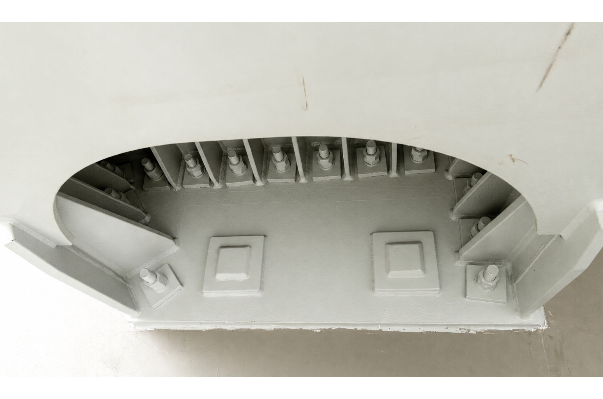
Another interesting structural detail was the design of the end joint at the intermediate support of the arch. The main challenge here was to transfer the bending moments and shear forces, which act simultaneously with the compressive forces in the arches, into the concrete substructure. To achieve this, high-strength steel bars with „hammer-head” ends, welded to the end plate of the arch, had to be embedded in the concrete of the pier. The arch segment had to be positioned with great precision in advance, before the second support was concreted in, followed by the installation of the reinforcement and the concreting of the support.
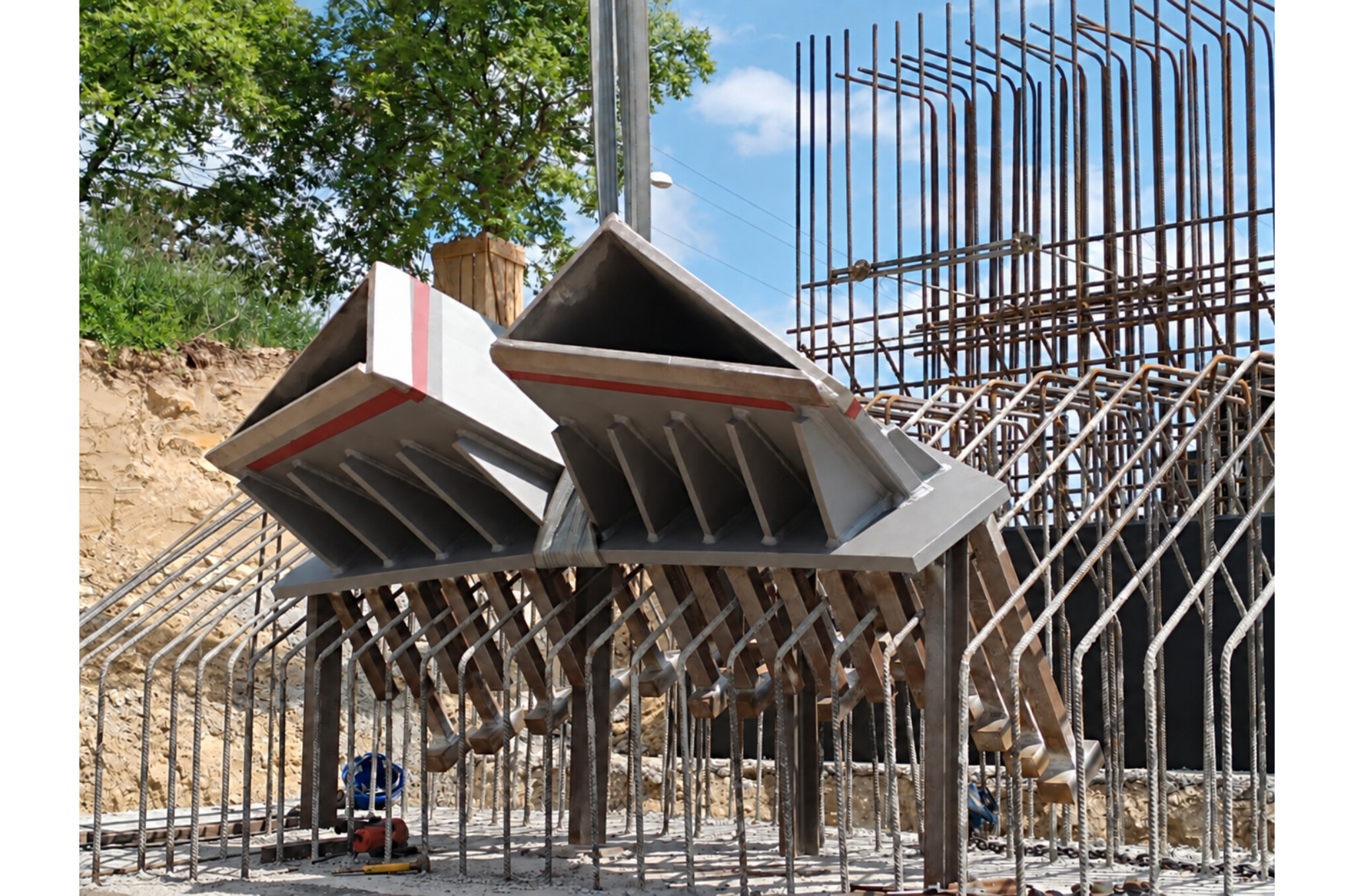
Arcs with a 56-degree angle of inclination
The bridge’s outward-curving arches offer a unique sight. Ádám Balogh explained that it is thanks to these that the bridge appears slimmer when viewed from the side, whilst at the same time the span-to-height ratio of the arch was likely to be much more favourable from a structural engineering perspective. The exact angle was determined by the geometry of the cut-out itself and the bridge’s effective width. The project manager added that their aim was to ensure that the intersection of the arches did not coincide with the abutment, thereby allowing for a cleaner steel structure at the junction. The 56-degree inclination angle, which appears to be random, was the result of these two boundary conditions.
Several variants were also examined when designing the bridge’s geometry. In addition to the open-web girder solution, a simple flat-steel suspension rod variant was also considered. Ultimately, the former was chosen on the basis of dynamic behaviour and aesthetic considerations.
Anna Mária Péter is also extremely proud of the design of the arched main girder, both in terms of the model and from a construction technology perspective. Due to the superelevation in the vertical and horizontal alignment of the arches, there was no pure arc either during construction or, consequently, during manufacture. The arched main girder has a closed, right-angled triangular cross-section. Due to the characteristics of the arch, the girder was constructed from two simply curved plates running perpendicular to one another and one doubly curved inclined plate. The fabrication drawings were prepared on the basis of a model created in the Tekla Structures programme. The model was modified several times in consultation with the contractors and the specialists overseeing the fabrication.
There was a contingency plan for every eventuality
Anna Mária Péter explained that the construction technology was developed in close collaboration with the engineers at the contractor Duna Aszfalt Zrt.. The bridge was manufactured by Duna Group’s Polish subsidiary, and the components were transported to the construction site by road.
Together with specialists in organisation and traffic engineering, they drew up a thorough and precise set of plans covering every possible scenario. Planning the on-site assembly posed a significant challenge, as the space available was very limited. The installation of the new bridge was condensed into two weekends, with the road completely closed for a maximum of 12 hours on each occasion.
Anna Mária Péter added that the traffic diversions and restrictions required for the bridge construction were planned by the traffic engineering specialists of FŐMTERV Zrt., whilst the diversions required for the parallel resurfacing works on the M7 were planned by the specialists of FLAVUS Mérnökiroda Kft..
Pedestrian and cycle traffic was maintained on the old bridge. The worksite was organised to ensure barrier-free access across the M7 motorway throughout the entire construction period.
The greatest challenge was the implementation of a full road closure on the M7 motorway, which was necessary for hoisting the bridge elements into place and for the demolition of the old bridge. Setting the dates and optimising the tight schedule required a great deal of creativity and compromise from all parties involved.
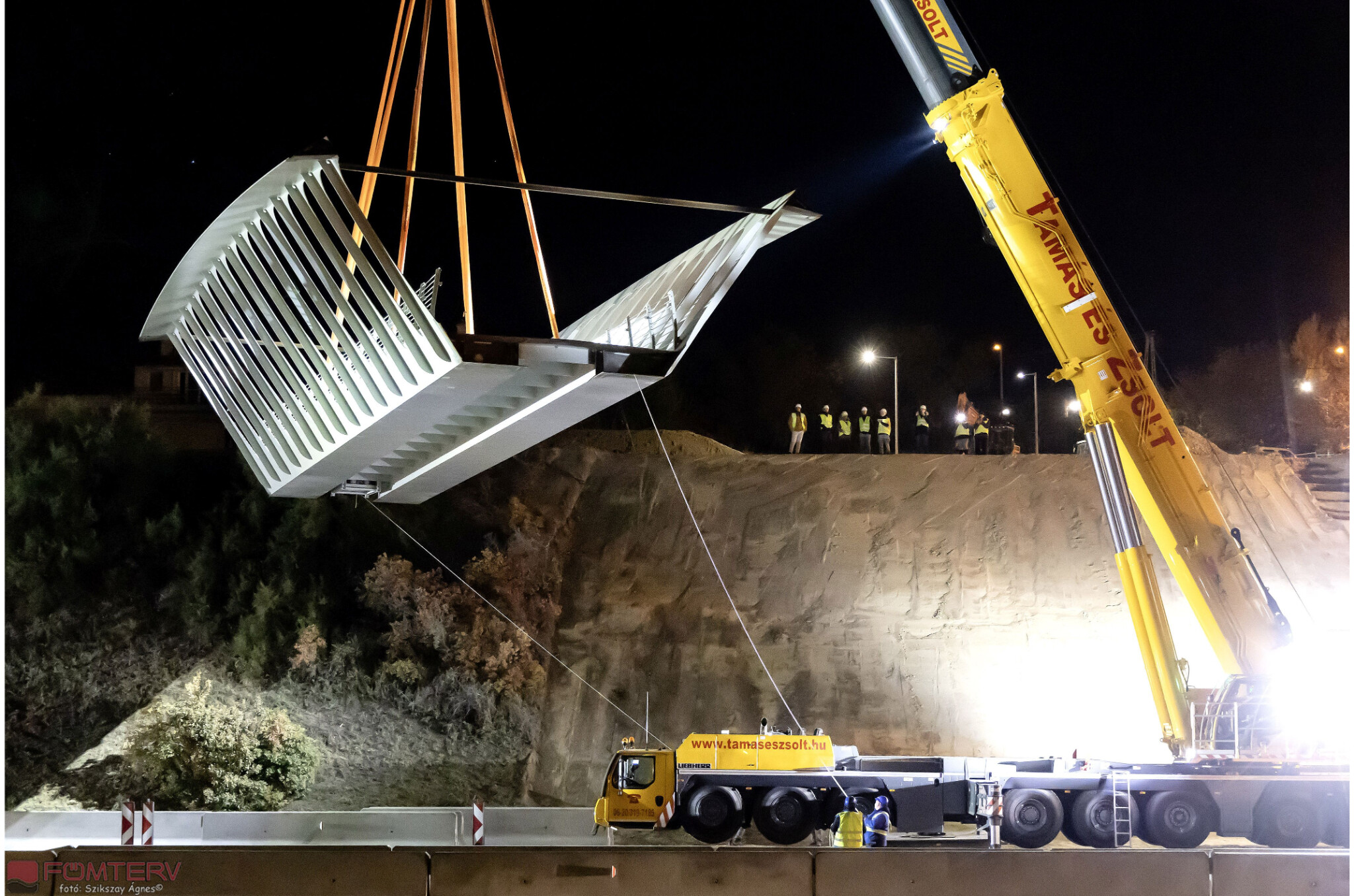
Its low kerb weight also posed a challenge when lifting it
The bridge sections were hoisted by crane onto the temporary trestles that had been erected beforehand. Every lift was a resounding success, thanks to the well-coordinated team of designers and contractors.
According to Máté Hazay, the most delicate and interesting aspect of the lifting operation was ensuring the stability of the temporary auxiliary trestles, given the structure’s relatively low dead weight of 193 tonnes. The arches are connected to the bridge deck by a perforated web plate. It was also necessary to take into account that strong crosswinds acting on the structure could jeopardise the stability of the structure whilst it was resting on temporary supports during construction. This also carried the risk that the temporary supports on the windward side might be lifted, causing the structure to topple over. The structural engineer explained that stability was ensured by spreading the supports out transversely. Consequently, they were positioned in an unorthodox manner alongside the track structure, adapting to the contractor’s existing auxiliary structures. The load from the superstructure was transferred to the temporary supports via closed-section bridging beams.
After the threaded rods had been tensioned and the on-site joints had been welded and protected against corrosion, the temporary supports were gradually removed in several stages. This phased approach ensured that the removal of the load from one support would not cause the failure of the other structures still bearing the load.
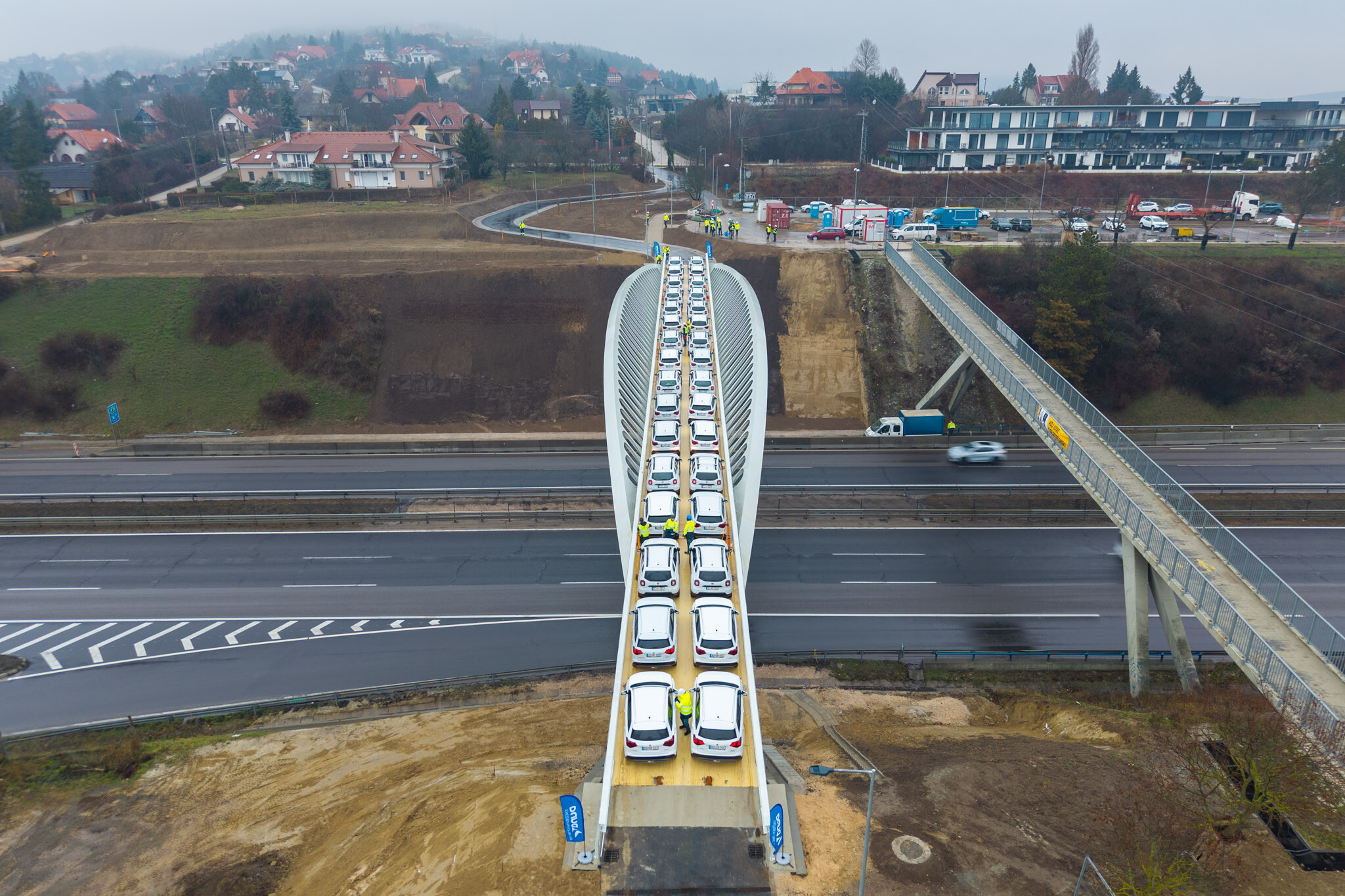
The bridge was also tested using cars and in a group convoy
Máté Hazay explained that the test loading was carried out by lecturers from the Department of Bridges and Structures (BME). On the bridge loaded with 32 passenger cars, the calculated deflection was within 0.1 mm of the measured results. He added that it was already apparent during the design phase that vibration dampers would need to be used on such a filigree footbridge with this span. The dynamic test loading was, in fact, the ultimate test of their effectiveness. For this, groups of 2, 10 and 32 people crossed the bridge in coordinated steps, jogging and running. The structure’s movements were measured by sensors, and observers were stationed at several points to assess the level of comfort on the bridge. During the dynamic load test, the maximum comfort level was recorded in most load cases. In some cases, the measured accelerations fell within the average comfort level range, which is also acceptable for such a slender footbridge.
Durability and ease of operation were also taken into account
The bridge’s corrosion protection was provided by a state-of-the-art, four-layer coating system. Ádám Balogh explained that, in addition, they endeavoured to take sustainability considerations into account from the very start of the design process. It is a common operational finding that drainage inlets often prove to be a source of localised faults; consequently, the bridge’s drainage system was designed so that, without these inlets, the cross-sectional area of the gutters at either end would be sufficient to drain all the rainwater collecting across the entire bridge deck. The cross-section of the stiffening girder box is shallow, so it is not accessible. For this reason, the entire stiffening girder, as well as the arches, have been constructed as airtight structures. The design ensures durability throughout the bridge’s entire service life, even without internal corrosion protection.
Source: Link






Spectacular arches, ingenious solutions – the designers of the FŐMTERV present Venice’s award-winning bridge

Fót and Dunakeszi are finally to get a cycle route linking the two towns

Renovation work is set to begin on dozens of public buildings in Terézváros

Test trains are rattling along the new Slovenian railway viaduct

Four new bridges to be built in the heart of the former industrial city

Rain gardens are coming to Budafok, with over 3,000 square metres of green space set to be developed

Contemporary art deco in Csopakon

Safer driving on the motorways: new digital signs for the MKIF
-

 Energy 2026. 09. 01.
Wind energy tenders are now open; technical compliance alone is not enough
-
What is being built? 2026. 09. 01.
There is good news regarding the Láng Negyed project – the investor has spoken out
-
Climate-X 2026. 09. 01.
A major US investment is boosting energy investment in Romania
-
Bound track 2026. 09. 01.
The SWIETELSKY Vasúttechnika Kft. has been declared the winner in two railway development projects