What is being built?
Many people from the capital are also choosing it as their new home: four buildings are being constructed in Gárdony using a special foundation system

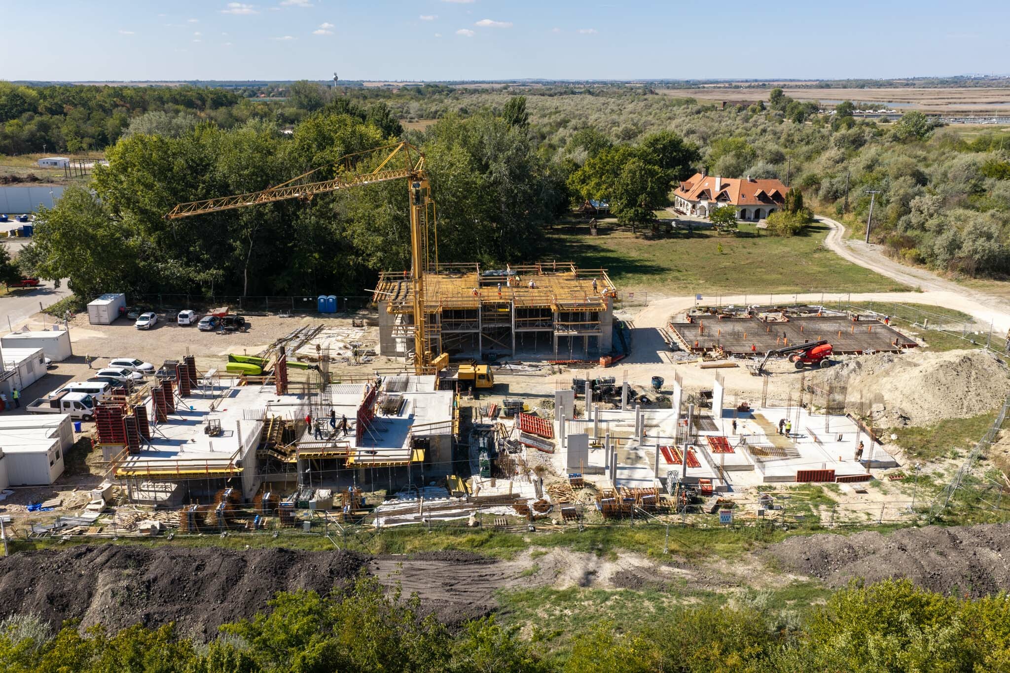
The KIRÁLYGÉM LAKÓPARK is being built in the Agárd district of Gárdony, approximately 250 metres from the lakeside, yet away from the busier town centre areas, in a suburban setting. The development site is bordered by Gém Street, Őrház Street and Mester Street.
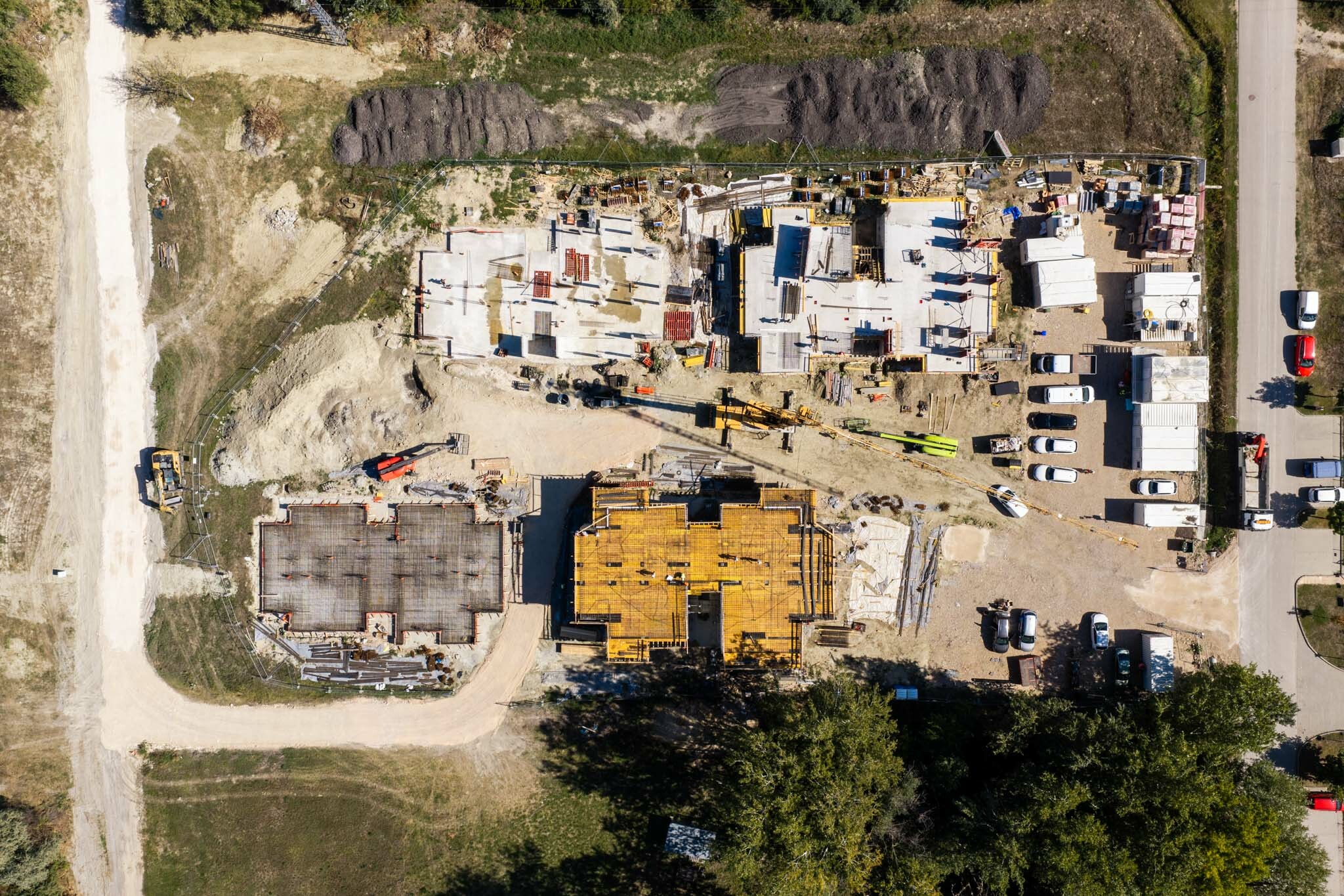
The worksite was handed over on 18 June 2026 to STRABAG, whilst the first major milestone in the structural works came a month later, on 20 July, with the start of work on the foundation slab. The project is currently still in the structural works phase, with completion at around 35–40 per cent.
The contractual deadline for completion is 31 July 2027, which, based on current progress, is on track to be met – project manager János Kovács told our newspaper.
Forty flats in four buildings of identical design
The residential complex will consist of a total of four three-storey buildings. Each building will have a floor area of 395 square metres and will accommodate ten flats, meaning that a total of forty homes will be built as part of the development.
The floor area of the flats ranges from 50 to 80 square metres. The ground floor and first floor have identical floor plans, but the second floor is different. There are recesses from the main façade, a green roof is being installed, and the number of flats is reduced from four to two.
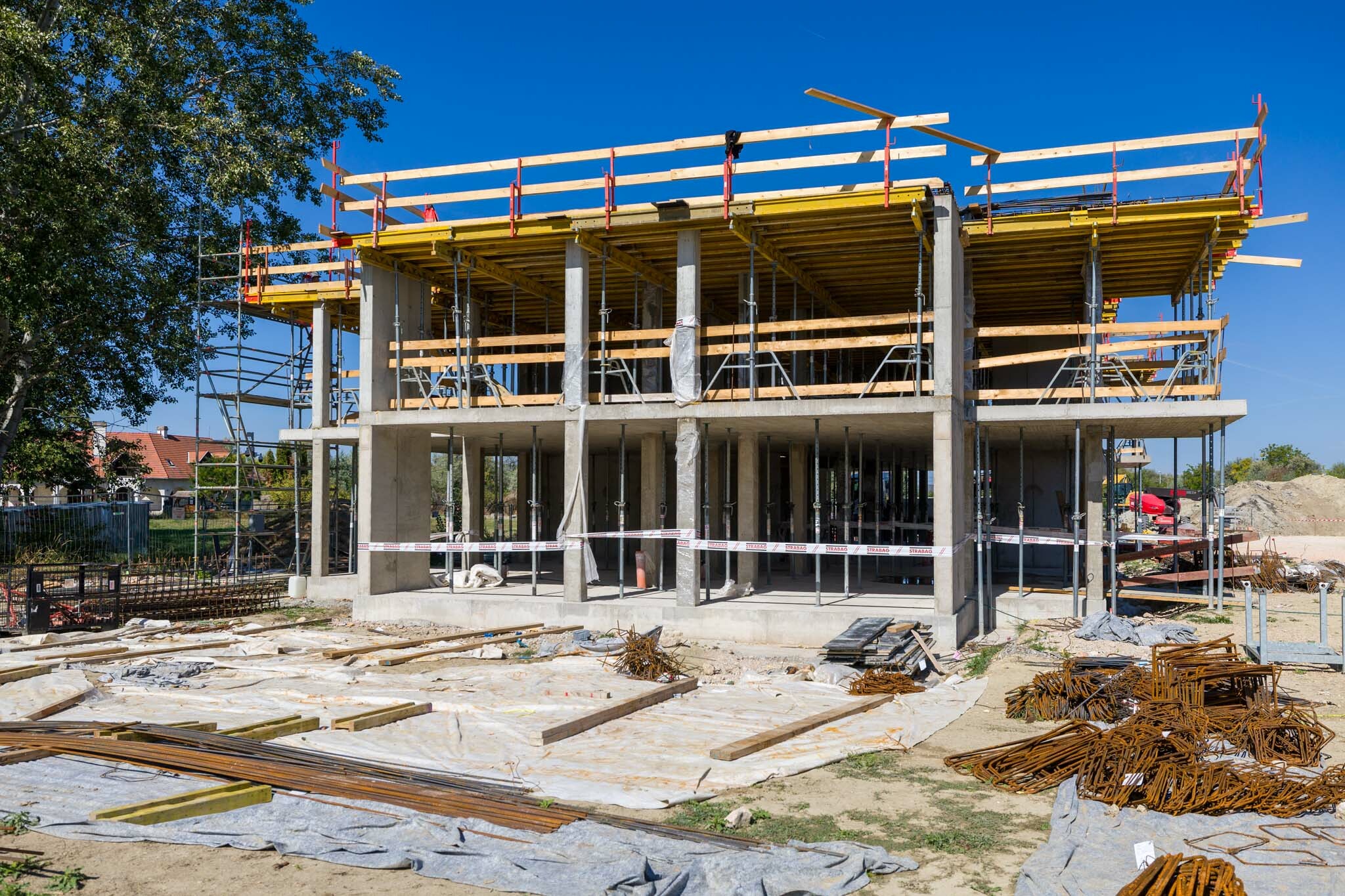
The floor-to-floor height of the buildings will be 3.10 metres, whilst the clear internal height of the living spaces will be approximately 2.70 metres. In the entrance halls with suspended ceilings and in the wet rooms, the internal height is estimated at 2.50 metres. Although the highest point of the buildings will be nearly 11 metres, the building height calculated in accordance with local regulations is only 6.97 metres. This complies exactly with the 7.00-metre limit for the zone.
The STRABAG is ready to use straight away
In addition to the construction of the four residential buildings, the STRABAG contract also covers the development of the entire site. The main contractor will hand over the development on a turnkey basis; in other words, the works range from internal utilities right through to landscaping and the construction of external roads.
Forty tree-lined parking spaces will be created on the site; each flat will have one parking space and a bicycle storage area. A sewerage network with a pumping station, a stormwater drainage system and the electricity supply will be installed, whilst solar-powered LED street lighting will be fitted in the outdoor areas.
Foundations tailored to the site’s conditions
A key part of the project’s planning was a detailed assessment of the site’s characteristics. As the residential estate is being built on land that had previously been reclaimed, the experts carried out detailed surveys of the site at an early stage of the planning process in order to determine the most suitable foundation solution for the buildings.
Accordingly, the local building regulations also require a geotechnical report to be drawn up. The soil investigation report Fugro Consult Kft., drawn up in 2021, was supplemented in May 2026 with dynamic probing tests, thus providing the designers with an up-to-date and detailed picture of the properties of the soil layers. This procedure enabled the precise identification of the soil conditions to which the foundations had to be adapted.
It was found that the upper part of the layer is loose, but at a depth of 5–6 metres it is already very compact and cemented. The area falls within seismic zone 3 and soil class „D”, whilst the groundwater is moderately aggressive towards concrete and is classified as XA2.
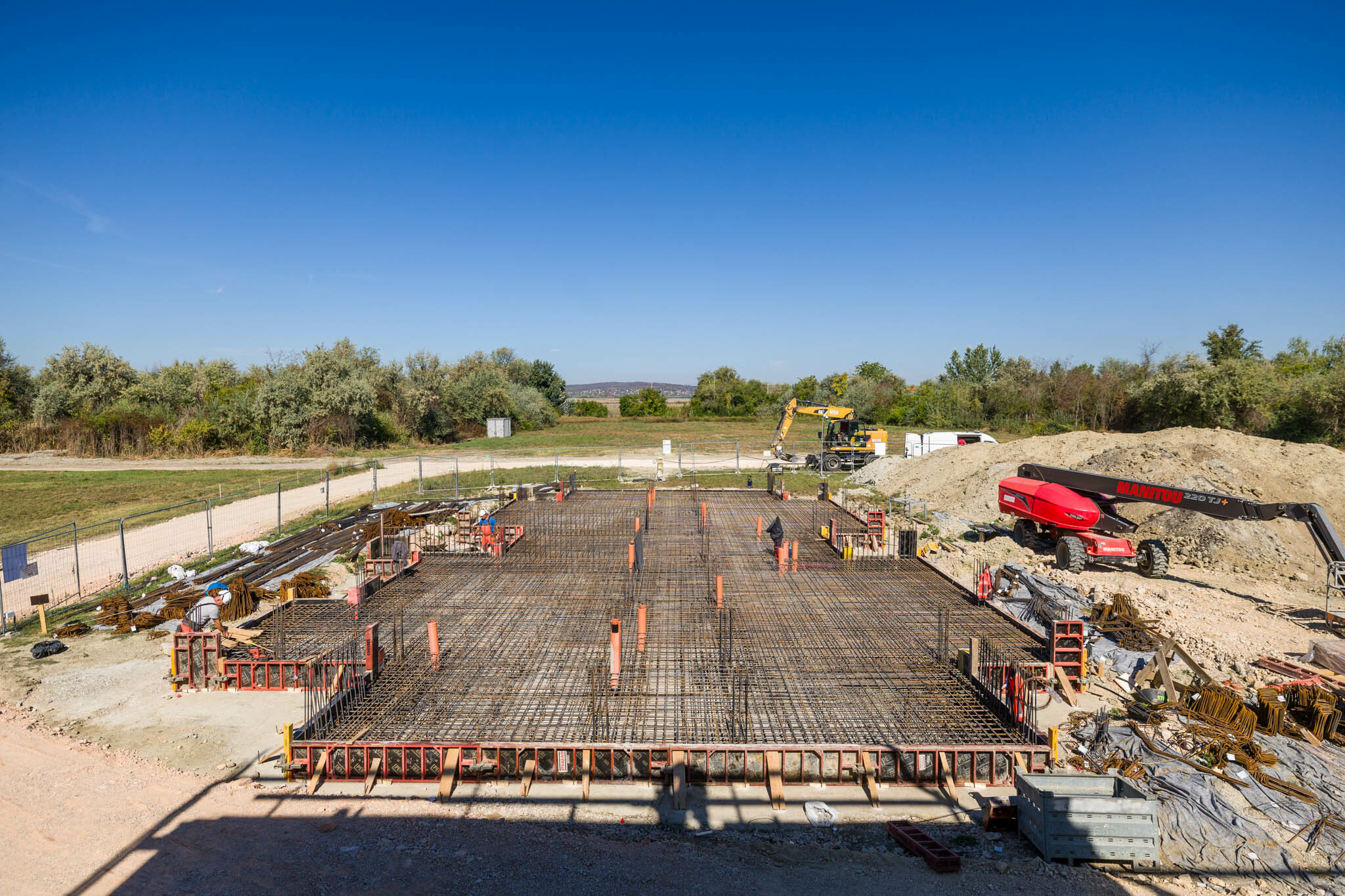
The foundation layer sequence had to be amended as a result of on-site measurements
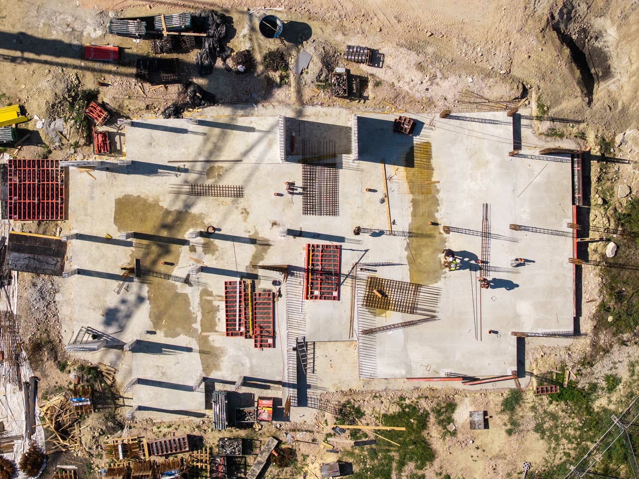
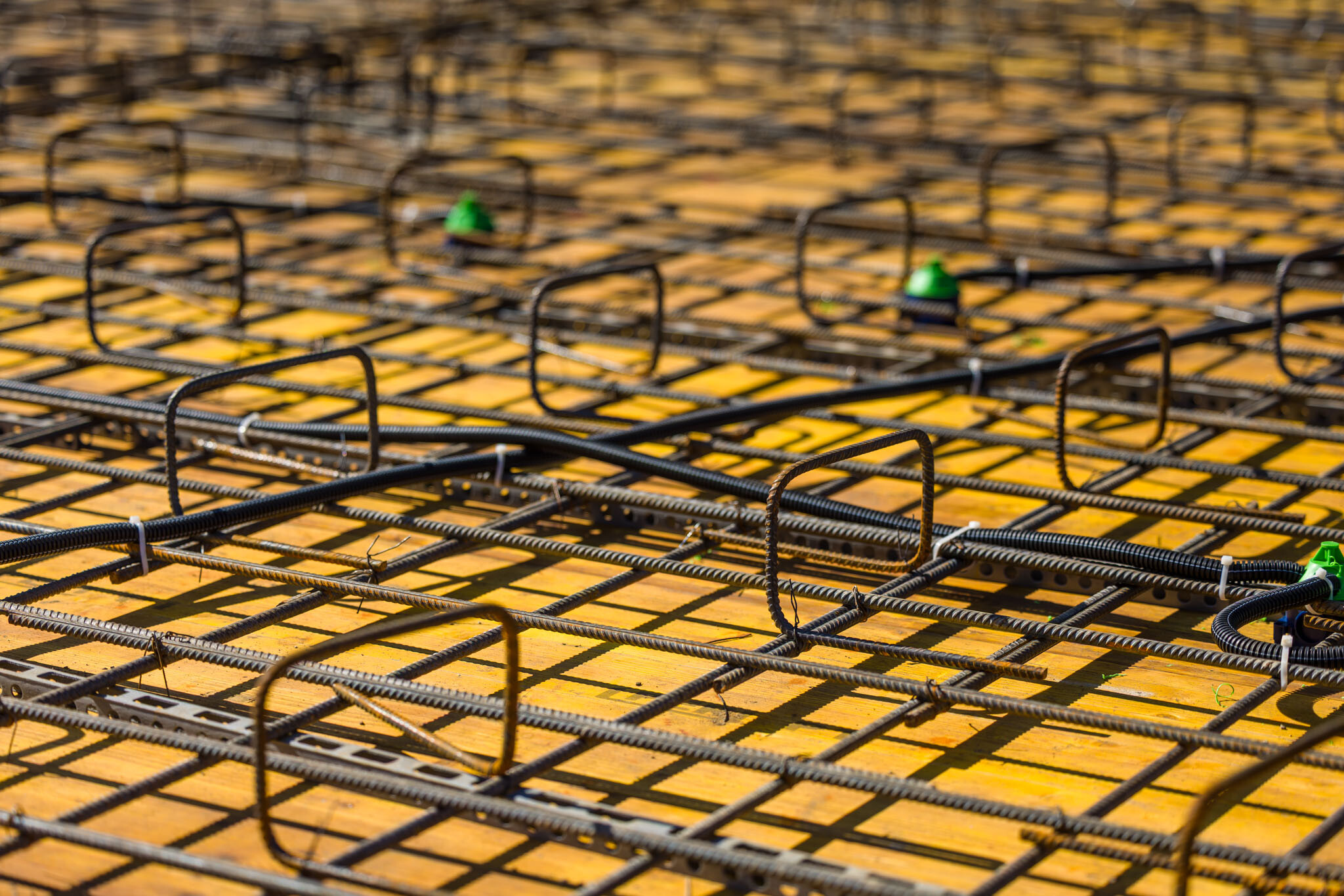
According to the original plans, the buildings were to have been constructed on a 50-centimetre-thick monolithic reinforced concrete slab foundation, beneath which a 60-centimetre-thick sub-base of crushed stone, compacted in layers, was to have been laid. The load-bearing capacity of this sub-base was to have been verified by disc testing to a value of at least E2 = 85 MPa.
However, on-site laboratory tests showed that this requirement was not met in all areas. This was the point at which the results of the soil mechanics tests had a direct impact on the construction work. In consultation with the structural engineer, the depth of the soil replacement was increased, and the foundations were constructed using a modified layer sequence.
According to the project manager, this has so far been one of the greatest construction challenges of the project. Due to the varying ground conditions, the contractor, the structural engineer and the laboratory had to work in close collaboration.
The groundwater did not cause any further difficulties with the foundations
Despite the unfavourable soil layers, the situation was simpler in at least one respect, as no significant groundwater was encountered during the foundation works. Measurements showed that only soil moisture was present below the foundation level. The reference groundwater level lies below the lower surface of the foundation slab, and as no cellar is being built, there was no need for either work area demarcation or groundwater level lowering.
Surface water and rainwater are managed via an open drainage system. Due to the characteristics of the groundwater, the base slab is constructed from C30/37-XC2-XA2 grade concrete. Protection against ground moisture is provided by modified bituminous steel sheet waterproofing, type Villas Elastovill E-PV 4 F/K Extra, on the plinth, which is extended at least 30 centimetres above the connecting ground level.
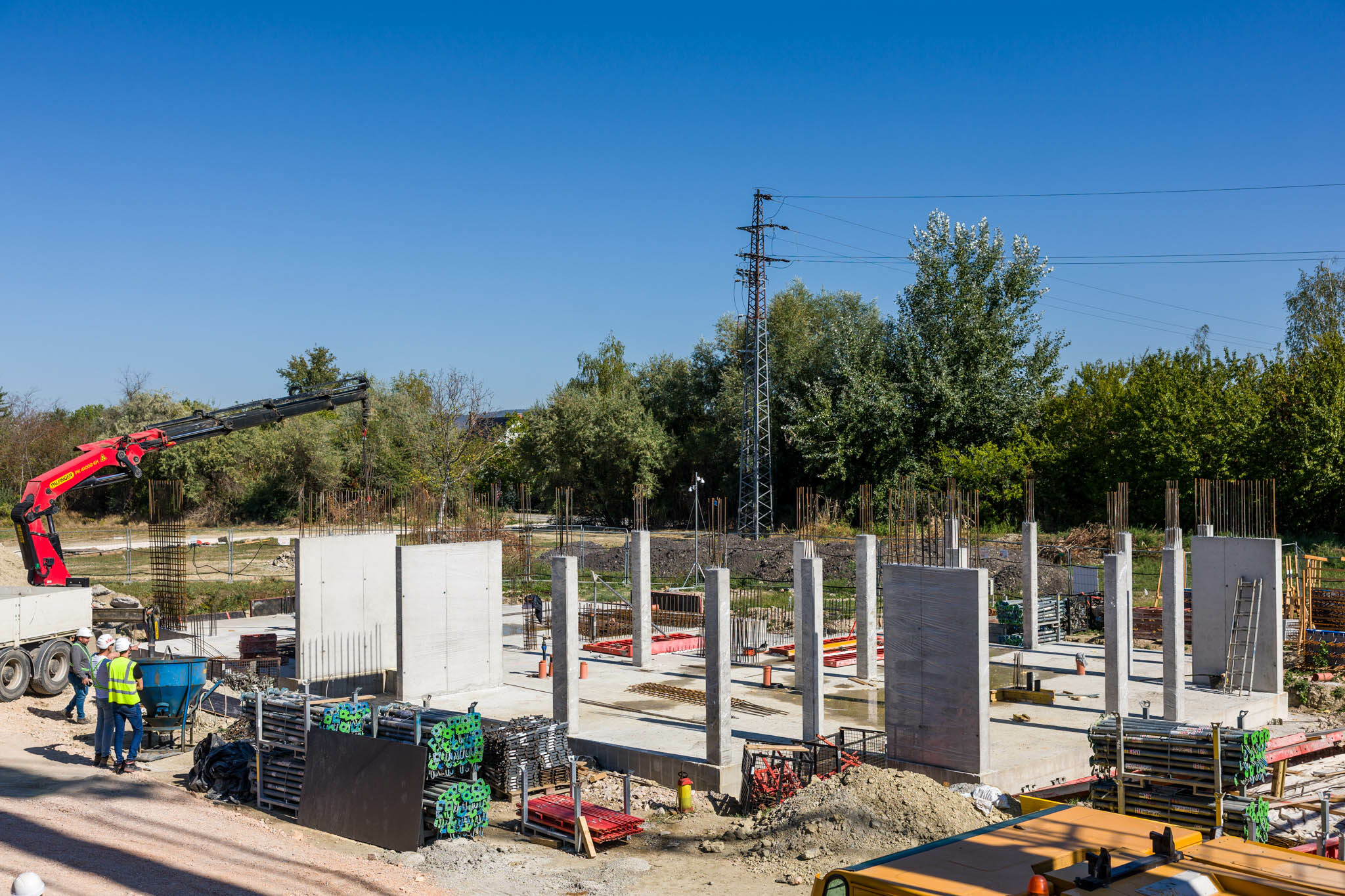
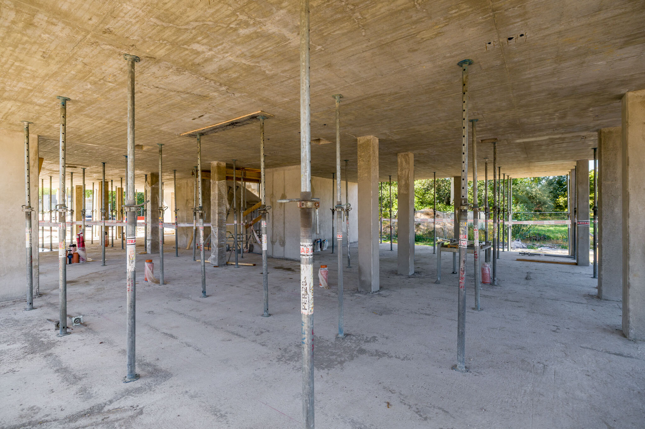
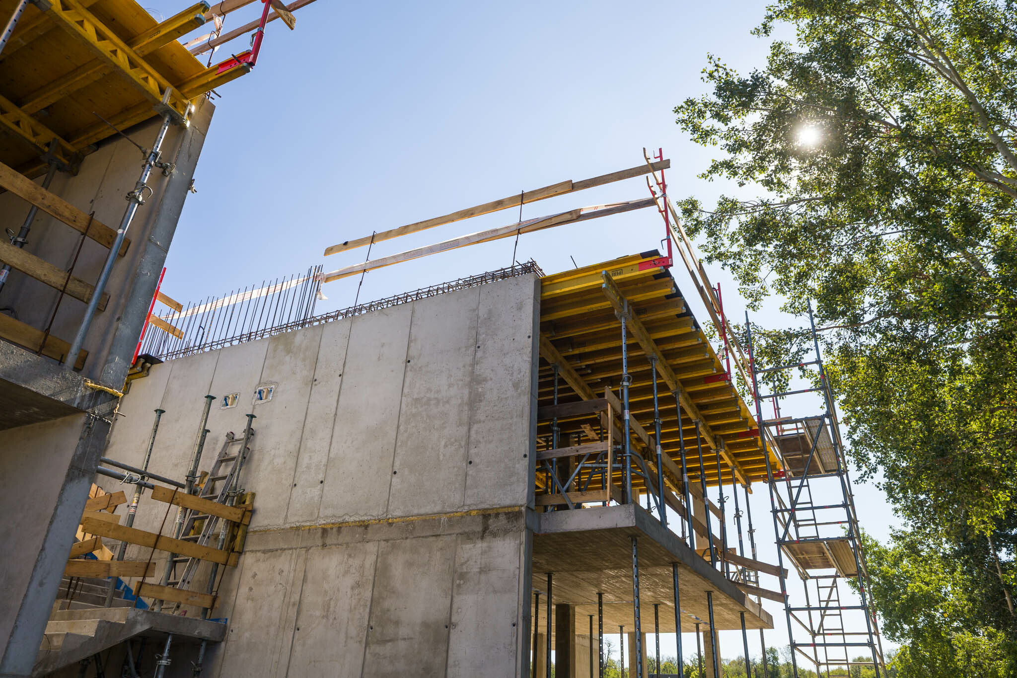
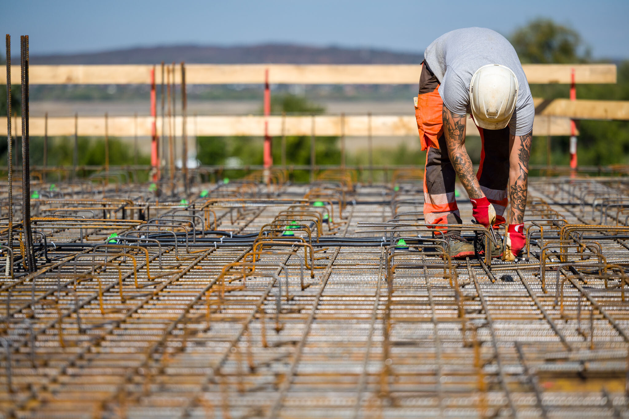
A monolithic reinforced concrete structure is being built using reusable formwork
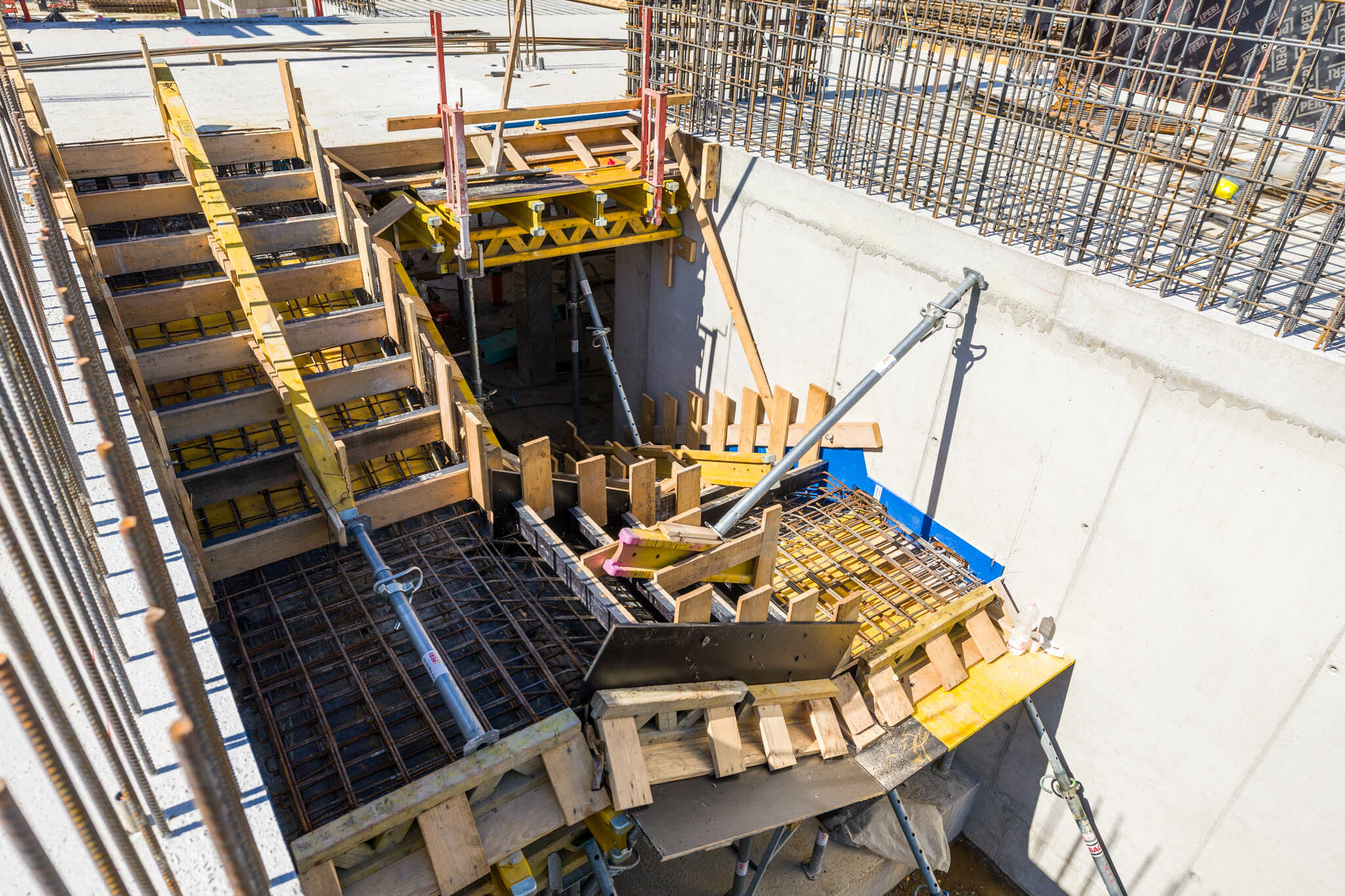
Following the challenges posed by the foundations, the structural work is now based on a highly repeatable system. The buildings are constructed with a monolithic reinforced concrete column frame, supplemented by bracing walls around the stairwell. The floor slabs will be concealed flat slabs with mushroom-head reinforcement, whilst the façades will be finished with Porotherm X-therm cavity-fill brickwork. No prefabricated structures are used. For formwork, PERI formwork technology is primarily employed. However, the construction of the four buildings is not taking place entirely in parallel. The buildings are being constructed in pairs, with a 1–2-week time lag between them, which, according to the project manager, enables efficient and rapid structural construction.
The design also contributes to this, as the four buildings are structurally identical, with two of them being mirror images of the other two. This means that the same formwork solutions can be reused.
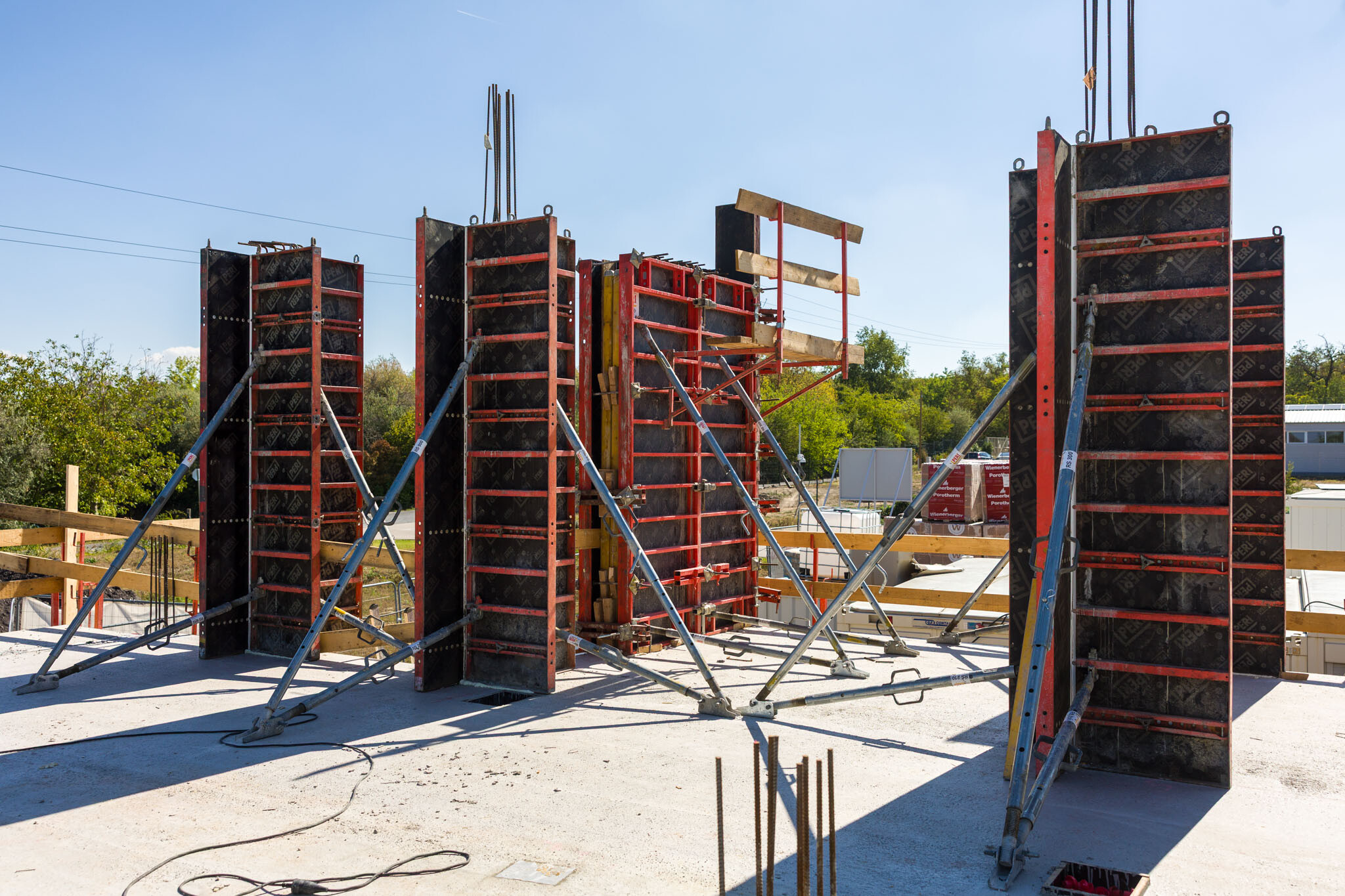
Around 2,500 cubic metres of concrete will be used in the buildings
The construction of the structures involves significant material requirements. According to preliminary calculations for the project, a total of around 2,500 cubic metres of concrete will be used, which amounts to approximately 625 cubic metres per building. On-site concrete supply will be provided by the Székesfehérvár site of the ROXIT concrete mixing plant, which is part of the STRABAG group.
Before structural work began, the routes for the mechanical and electrical services beneath the base slab and the connection point for the water supply network had already been prepared. Further mechanical and electrical penetrations are currently being prepared in accordance with the design shown in the structural engineering plans, in consultation with colleagues from the relevant disciplines where necessary. Installation work by the mechanical and electrical teams has not yet commenced.
Not all roofs are the same: pitched roofs, terraces and green roofs are all being built
Once the structure is complete, the character of the buildings will be defined by a variety of roof designs. The pitched roofs, with slopes of 10 and 20 degrees, will be clad with Prefalz standing-seam aluminium roofing, with rainwater drained away via gutters.
On the second floors, however, there are also accessible terraces and green roofs. The green roofs have a 2 per cent gradient, sloping towards a single point, with drainage provided by gravity-fed gullies. The accessible terraces slope outwards and have external drainage.
Both flat roofs will be waterproofed using FATRAFOL PVC, which will be folded up at least 30 centimetres onto the adjoining walls. The green roofs are bordered by a 20-centimetre-thick reinforced concrete parapet wall, with thermal insulation and aluminium cladding fitted on both sides.
However, green roofs are not merely a visual feature. According to the calculations, 60.67 square metres per building count towards the mandatory green space requirement at a quarter of their actual area. As a result, the project meets the 55 per cent green space requirement; the calculated figure is 55.06 per cent.
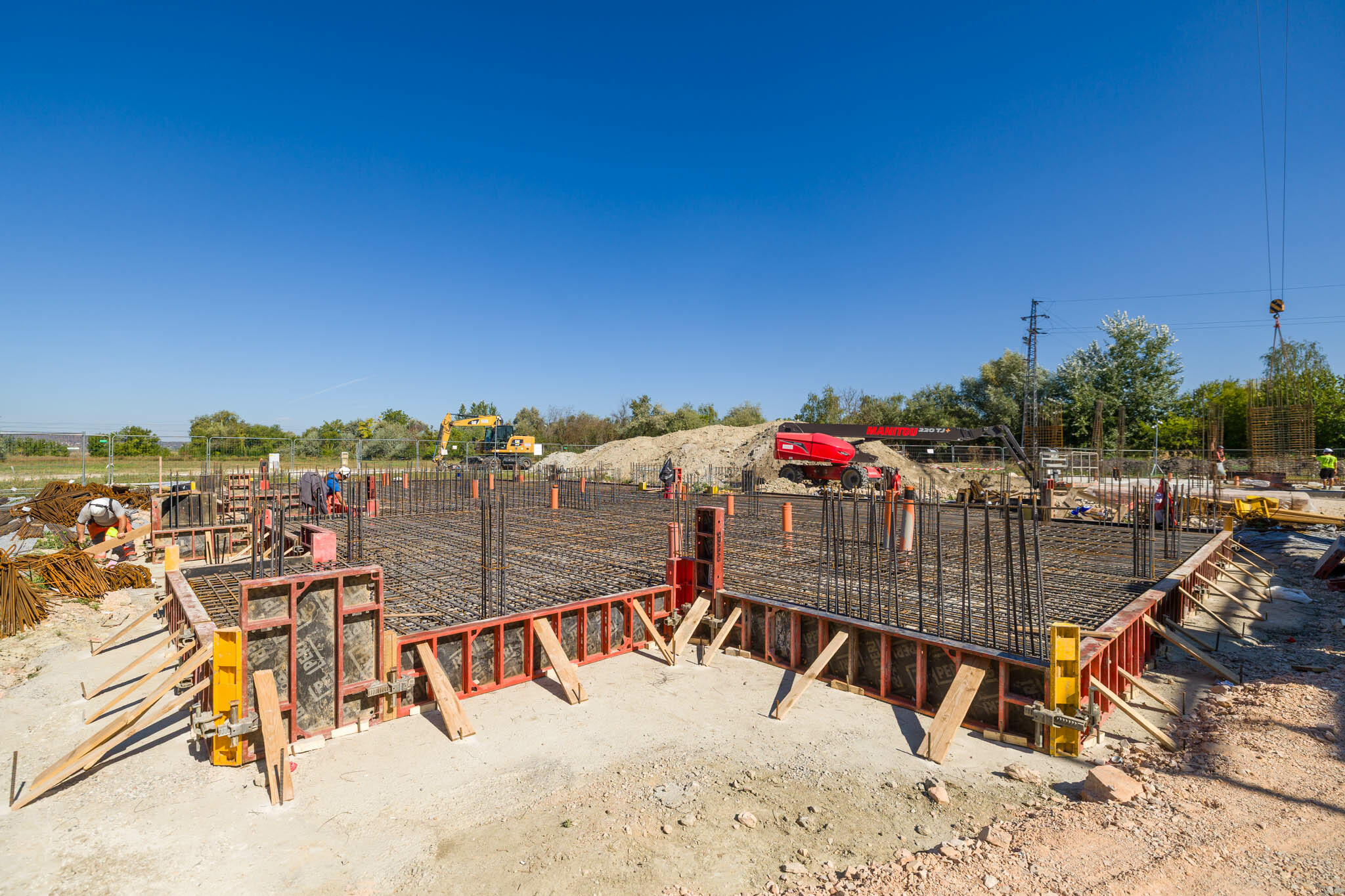
When it comes to soundproofing, attention is paid not only to the walls but also to the stairs
In residential buildings, not only the structural design but also sound insulation between flats is a key consideration. The walls separating the flats are constructed from 30-centimetre-thick Porotherm AKU Z sound-insulating elements.
Grooves no deeper than 5 centimetres may be cut into the walls; where grooves are cut on both sides, they must be offset. Horizontal grooves are not permitted. A 3-centimetre-thick layer of EPS sound insulation is installed in the upper-floor screeds, and the screed is laid with expansion joints between rooms.
Sound-insulated partition walls and shaft walls have also been incorporated at critical points to ensure that the mechanical services do not compromise the sound insulation of the structures separating the flats. One interesting aspect of the sound insulation is the stairwell. The stair stringers are connected to the walls using Schöck Tronsole elements, which provide acoustic separation. The aim is to ensure that as little of the footfall noise generated in the stairwell as possible is transmitted into the flats. The sound insulation of the flat entrance doors is Rw+C = 33 dB.
Three heat pumps per building provide heating and cooling
At the heart of the housing estate’s energy system are three Mitsubishi PUZ-SWM140YAA air-to-water heat pumps per building.
The equipment operates as a split-system; the outdoor units are installed on the roof, whilst the indoor hydromodules and the ERSF-MEE units are housed in the plant room on the first floor.
The outdoor units are mounted on vibration-free supports and fitted with a thermostat-controlled, electrically heated drip tray. This serves to drain away de-icing water and prevent ice from forming on the roof during winter operation.
The mechanical engineer has limited the noise emissions from the equipment to levels below the limit values specified in MSZ 18150 and Decree 27/2008 of the Ministry of Environment and Water Management and the Ministry of Health. A static live load of 5 kN/m² was assumed for the mechanical engineering spaces.
An important scheduling consideration during construction is that the support beams, as well as the roof penetrations for refrigerant and electrical cables, should be secured before the insulation layers are completed. This ensures that the continuity of the waterproofing is maintained.
The machines are supplied with power from a separate „HE” heat pump distribution board, with a 3×50 A H-tariff. A service area specified by the manufacturer is left clear around the equipment to allow for future maintenance.
Underfloor heating and fan coils that can be controlled individually for each flat
A buffer tank is installed between the heat pumps and the radiators in the flats. From here, the heating and cooling water is distributed to the individual flat’s distribution and return manifolds. During the winter, underfloor heating operates at 36/30 °C. A 10-centimetre pipe layout is used in the bathrooms and a 15-centimetre layout in other rooms, whilst the bathrooms are equipped with 300-watt electric towel rails.
In summer, high-sidewall fan coils operating with cooling water at 7/12 °C provide cooling. An important feature of the system is the ability to control it on a flat-by-flat basis. Each room is assigned a separate circuit on the manifold, and the temperature is regulated by programmable room controllers via motorised valves. Domestic hot water is also produced centrally from two 657-litre storage tanks heated by heat pumps, with supplementary heating provided by electric heating elements. Cold and hot water consumption is measured by sub-meters for each flat.
Triple-glazed windows and a state-of-the-art IT network
In addition to the building services, the building envelope also serves energy-efficiency objectives. The flats will be fitted with triple-glazed, argon-filled plastic windows with 6–7 air chambers, with a Uw value of 1.10 W/m²K. The windows will be patina grey on the outside and white on the inside, and will feature roller shutter boxes and built-in fly screens. Louvered shading will also be installed on the top floor.
The front doors to the flats are multi-point locking, steel-reinforced security doors. The living rooms will have laminate flooring, the wet rooms will have non-slip ceramic tiling, and the bathrooms will be tiled up to a height of 2.10 metres.
On the electrical side, each flat will have 3×16 A available, with an electric hob and oven. The low-voltage system includes much more than this. The flats will also be fitted with fibre-optic connections, a Cat.6A structured cabling system, Wi-Fi, cable TV and an intercom. The rack cabinets will be designed to accommodate both alarm and CCTV systems.
A dedicated extraction system ensures air circulation in bathrooms and kitchens
No central air-handling system is installed for the ventilation of the flats. Air is extracted from the enclosed bathrooms, toilets and kitchens using individual fans, such as the Helios ELS or equivalent units.
An air flow rate of 60 m³/h is assumed for wet rooms and 300 m³/h for kitchens. The fans are activated by a light switch or by humidity and presence sensors, with a start-up delay of approximately one minute and a run-on delay of 5–6 minutes.
Extraction alone is, of course, not sufficient; air must also be supplied. This is ensured by air intake elements built into the window frames.
The fans are fitted with non-return valves; a separate non-return valve is fitted to the kitchen air ducts, whilst a fire-rated non-return valve at the connection to the shafts prevents the spread of fire between storeys. The extracted air is channelled through the shafts and discharged above the roof.
The installation of the air barrier begins before the thermal insulation is fitted
When it comes to energy performance, it is not just the thickness of the thermal insulation that matters. It is just as important that the building is properly airtight.
A 0.6-centimetre air barrier base coat is therefore applied to the Porotherm X-therm masonry before the thermal insulation is installed. The façade is generally insulated with 10 centimetres of EPS, whilst the reinforced concrete walls are insulated with 15 centimetres of graphite-reinforced EPS.
The balconies are connected to the floor slab using Schöck Isokorb thermal break connectors. During construction, particular attention must be paid to ensuring that thermal insulation layers of different thicknesses are levelled, and to the design of the plinth and window and door joints.
A 10-centimetre-thick layer of XPS will be installed on the plinth. The final façade finish will be a 1.5–2-millimetre-thick thin-coat render in off-white and smoky brown colours, with textured accents. This will be complemented by patina-grey windows, aluminium cladding and Prefalz standing seam metal roofing.
The technical documentation also specifies particular manufacturers
One distinctive feature of the technical specifications for Királygém Lakópark is that the detailed design documentation specifies particular manufacturers and products for several major structures and pieces of equipment. The documentation includes, amongst other things, Porotherm masonry units, Austrotherm and Knauf thermal insulation, FATRAFOL waterproofing, Schöck thermal bridge breaks, Prefalz roofing and Mitsubishi heat pumps.
A technically equivalent product may only be installed following consultation with and approval by the designer. This is particularly interesting because the specific product names listed on the housing estate’s website are therefore not merely for illustrative purposes. According to the project manager, they reflect the actual technical specifications set out in the plans.
The A+ energy rating is achieved through a combination of the building envelope and the building services
The housing estate is being built to an A+ energy efficiency rating. Neither thermal insulation nor heat pump technology alone would be sufficient to achieve this. The building’s energy performance is determined by the combination of the building envelope and the mechanical systems.
The façade will be fitted with 10–15 centimetres of EPS thermal insulation; the loft ceiling will have 2×15 centimetres of rock wool; the terraces and green roofs will have layers of PIR and EPS; and the ground-level floor will have 12 centimetres of EPS.
This is complemented by triple-glazed windows with a Uw value of 1.10 W/m²K, balcony connections with thermal breaks, additional XPS insulation in front of the floor slabs and columns, and an airtight base render.
On the mechanical engineering side, heating, cooling and domestic hot water are provided by air-to-water heat pumps that utilise renewable energy. Low-temperature underfloor heating (36/30 °C) and room-by-room control are also part of the system. There are no chimneys in the buildings and no fossil fuel combustion takes place.
To ensure energy efficiency compliance, the declarations of performance for the materials installed are checked during construction, including those for thermal insulation and the Uw values of windows and doors. Concealed building services are approved by the designer and documented with photographs before being concealed, and the commissioning of the systems is recorded in a report. Final compliance is confirmed by an energy performance certificate issued on the basis of the as-built condition.
A substantial fleet of machinery is also being used on the construction site
The construction of the housing estate is complex not only because of the technologies involved. The work on site is characterised by constantly changing machinery requirements.
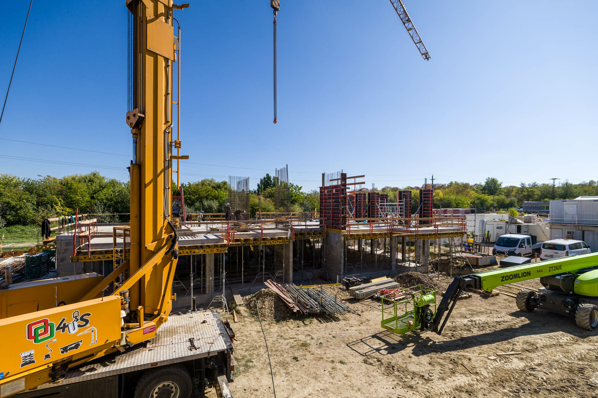
A fleet of machinery, comprising both company-owned and hired vehicles, is being used for the construction work. During the current structural works phase, a Manitou all-terrain forklift, a boom-type personnel lift and a mobile crane are operating on site, whilst self-loading lorries and KCR vehicles are also constantly moving around.
In the coming weeks, however, it will not only be the reinforced concrete structure that dominates the site. From week 40 onwards, as the infill walls are erected, the buildings will gradually begin to take on their final shape.
Source: Link








The Buda interchange could also be extended northwards

A railway bridge will link the sections of the Tokaj-kör route: cycling infrastructure development in the wine region continues

Many people from the capital are also choosing it as their new home: four buildings are being constructed in Gárdony using a special foundation system

One of Abony’s most important transport routes is to be redesigned

Four new bridges to be built in the heart of the former industrial city

Rain gardens are coming to Budafok, with over 3,000 square metres of green space set to be developed

Contemporary art deco in Csopakon

Safer driving on the motorways: new digital signs for the MKIF
-

 Current at 2026. 09. 09.
A first-hand look at a career in engineering – Duna Group Szabadegyetem is back
-
Climate-X 2026. 09. 09.
Nyíregyháza Spartacus FC goes green – four hundred solar panels to be installed on the stadium roof
-
Bound track 2026. 09. 15.
Nearly 50,000 people travel on it every day – the refurbishment of the Cegléd main line continues
-
Current at 2026. 09. 09.
Rental flats, Rákosrendező, decentralisation – important ideas were put forward on the Real Estate Beach Conference stage